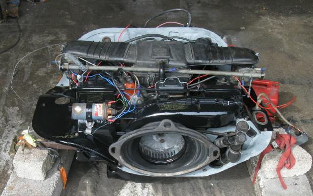
I decided to rebuild the engine so I would not have any worries about its reliability. I brought it home in the back of a small hatchback so that I could work on it in more comfort. However, progress was slow and an opportunity arose to buy a newly rebuilt engine at a very reasonable price, so I collected this in June 2012. Here it is sitting on the garage floor before I collected it.
However, things didn’t go according to plan. The engine in my Californian Variant died when the distributor fell apart and it didn’t like the replacement. I ended up swapping this engine into it and ran it for a while until it caught fire (another long, sad story) and I used it for spare parts. I eventually rebuilt the original engine with twin carburettors and sold the car on.
The story of the original engine rebuild continues below.
 Anyone who has a Type 4 will know that the original Haynes Manual for the car only covered the 1700 (1679 cc) models, it didn’t cover the 1800 engine, so anyone with a 412LS will be out of luck. However, the 4-cylinder version of the VW-Porsche 914 produced from 1969 to 1976 used the same engines as the VW412 and then had a 2 litre engine after the 412 ceased production. Haynes also produced a manual for this car, the 914-4, that covered all the engines fitted including the 1800 (1795 cc) twin carburettor engine used in my 412LS. I expect they also produced a manual for the 6-cylinder 914-6 but I never bothered looking for it and both will be long out of print by now. However, in March 2008 I managed to obtain a later reprint of the Haynes Manual that included a five page supplement with details of the 1800 engine. The detail is pretty sparse, no coverage of a rebuild, and there are no photographs but, nonetheless, worth getting to complete my collection.

 The Type 4’s 1800 engine completely filled the hatchback I was using as a runaround at the time. It’s well packed with cardboard to ensure the boot carpeting wasn’t damaged. With a little bit of ingenuity I unloaded the engine and placed it the bench in my garage along with some spares, there are more on the floor out of sight. The lifting slings are still draped around the engine.
 I spent a whole day sorting out the garage and managed to more than double my bench space.
 The worktops now extend down the whole side of the garage and everything is now off the floor. I also installed an extra couple of strip lights so that I can see what I’m up to. The engine stripped down as far as I could get without splitting the crankcase – which was firmly stuck after 30 years. I couldn’t split the crankcase without the special tool I bought from VW Heritage. This shows the tool installed in the aperture for the oil pump. It’s very simple but very effective. Now all I have to do is to tighten up the silver coloured nut in the middle.

 When the case didn’t split easily, I realised that there had to be some more studs still not undone. After looking again, I found three more tucked away on the left hand side. After undoing those, the case opened up nicely like this. But I have to remove the pistons before I can go any further, they won’t go through the openings in the crankcase.
 Here are the two halves opened up with the crankshaft and camshaft still in place in the left hand half.
I shall be following the order of overhaul and reassembly more or less as set out in my Haynes Manual for the car. The differences being that they rebuilt one with fuel injection and manual transmission and I am rebuilding one with carburettors and automatic transmission. I will have to keep my wits about me to avoid missing something.
 I had decided to replace all the bearings “just in case” to give me peace of mind about the engine’s reliability. Here I have drawn off the two gear wheels for the camshaft and the distributor from the back end of the crankshaft so that I can replace the end bearing. The connecting rods are still in place.
My next job was to clean the outside of the crankcase thoroughly, it was well coated with a hard baked layer of oil and dust which took some shifting. My initial attack with a proprietary cleaner followed by a pressure washer didn’t shift it all so I realised that I needed something stronger to shift the rest. I tried brushing on some petrol which seemed to do the trick. It managed to penetrate the baked gunge but needed several applications and a stiff brush to shift it.
I also needed to clean my bench before I started reassembling things to avoid contamination.
Replacing the big end bearings was straight forward but getting the camshaft gear drive wheel back on proved tricky. The book says, quite glibly, to heat the gear up to 85°C and then press it back onto the shaft. So I placed the gear into a saucepan of water which I brought to the boil for a couple of minutes and tried placing it over the shaft. It was clearly not going to work and I didn’t want it to get stuck halfway on. My eventual solution was to find a short off-cut of scaffold tube and very carefully dress the end square, to act as a drift. I then put the gear back on at a fast boil for half an hour to ensure it was thoroughly heated through. After liberally coating the shaft in engine oil and carefully lining everything up again, the gear slipped on beautifully. I then applied more engine oil to the gear itself and was confident that the residual heat would ensure that any remaining moisture would be driven out without leaving any corrosion.
I then replaced the remaining bearings, placed the crankshaft and camshaft in correct mesh, and reassembled the two halves. Following the book’s advice, I checked for free rotation before fully tightening up and was most dis-chuffed to find that it was binding. It’s a good job that I did check as I found that the centre shell bearings weren’t seated properly. After a couple of attempts, all was well and I torqued up the crankcase progressively, checking the crankshaft’s rotation as I went.
I was left wondering how VW managed to assemble everything in the factory, I found it quite a juggling act to stop things falling out when lining up the crankcase halves on the long studs!
 The next job was to install the flywheel. This involves setting the crankshaft end-float by adding shims which are available in a very restricted range of thicknesses. They are now like hen’s teeth but I was able to round up enough and carefully measured my end-float.
After partially torquing up the first three of the bolts I found that my end-float had disappeared so everything had to come off again. This is not made easy because the shims are captive behind the flywheel oil seal which also has to come out again.
After a few more iterations I ended up with an acceptable end-float and a nicely torqued flywheel. Or, actually, not a flywheel but a torque converter drive plate as seen here. Yes, I’m installing the automatic gearbox from the Californian Variant.
The next job was to install the pistons, cylinders and cylinder heads. These went on without too much difficulty, the main challenge was compressing the piston rings because all of the standard tools for the job seem to assume free access to the top of the piston as it is lowered into the cylinder. For the VW engines, the pistons are caged in by the four studs as the cylinder is pushed on from the top. So some imagination is called for.
Fitting the tinware was a challenge. I had a selection of pieces and found that there were significant differences in the holes provided in the front plate for carburettor and fuel injection models and there was an additional hole for the automatic gearbox dipstick tube. Every piece needed cleaning, derusting and painting and I splashed out in a set of shiny new tinware screws.
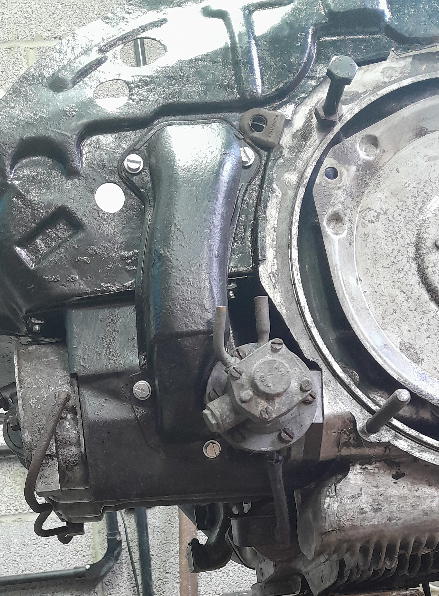 This is one example of a wrinkle not covered in the Haynes manual – the front right lower cover plate has to be installed before the fuel pump is installed but the vertical warm-air duct for the preheat has to be installed afterwards. You cannot reach the top bolt if the duct is installed first. It is a very snug fit here.
By the way, the black bolt installed in the upper mounting hole is to protect the drive plate when I tip the engine up to install the exhaust and tinware to the underside. There is one each side.
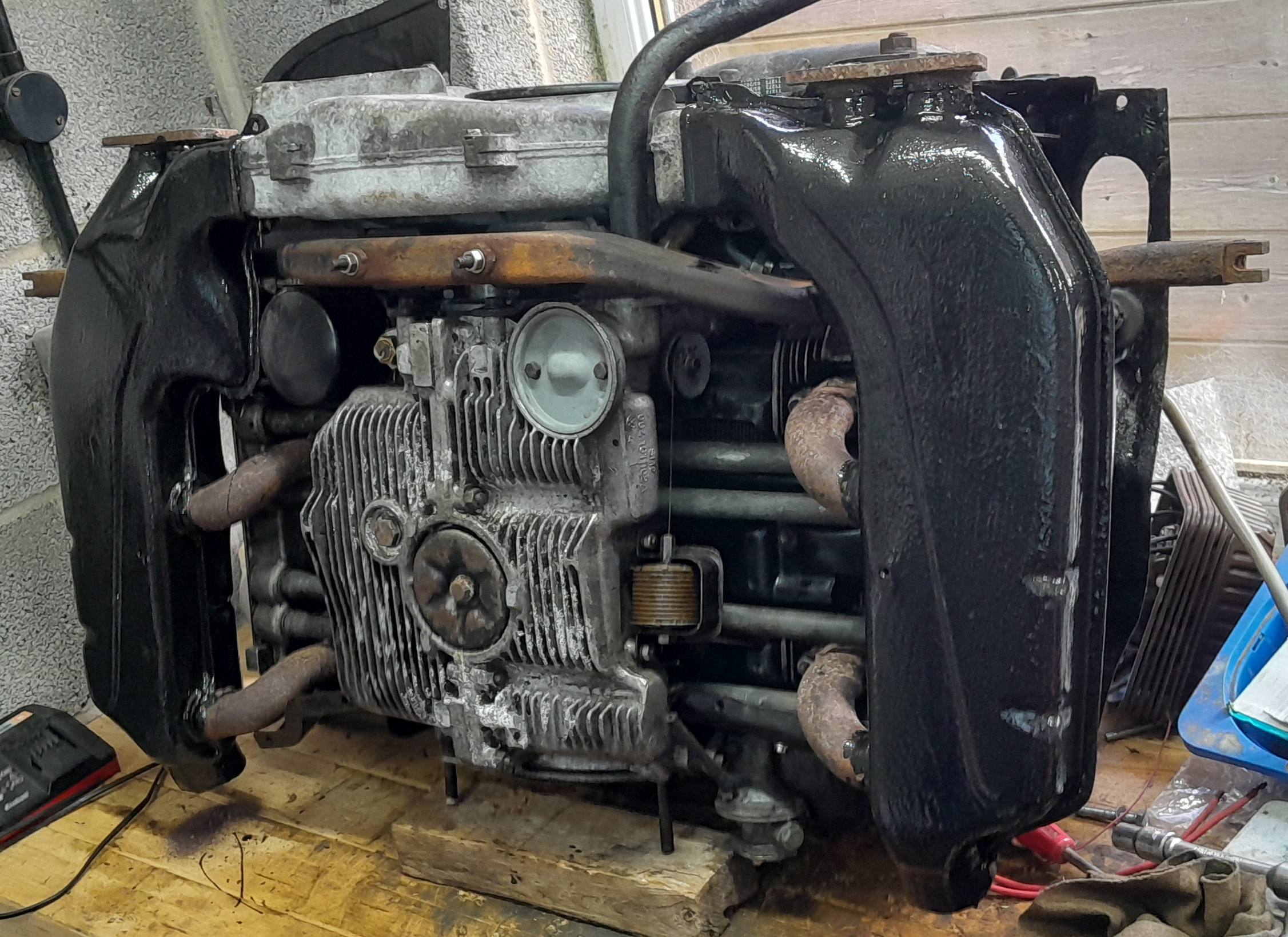 I had obtained a pair of transporter heat exchangers from Jane Terry so that I would not have to rely solely upon the Eberspächer heater. I fitted them in place and found that they would not fit within the car’s tinware. They are quite a bit larger and project a couple of inches further forwards. So that gave me the dilemma: do I fit the standard heat exchangers or do I try and source transporter tinware or do I start metal bashing.
I didn’t want to lose my good heat exchangers and transporter tinware seems to be a bit of a minefield so I chose metal bashing! 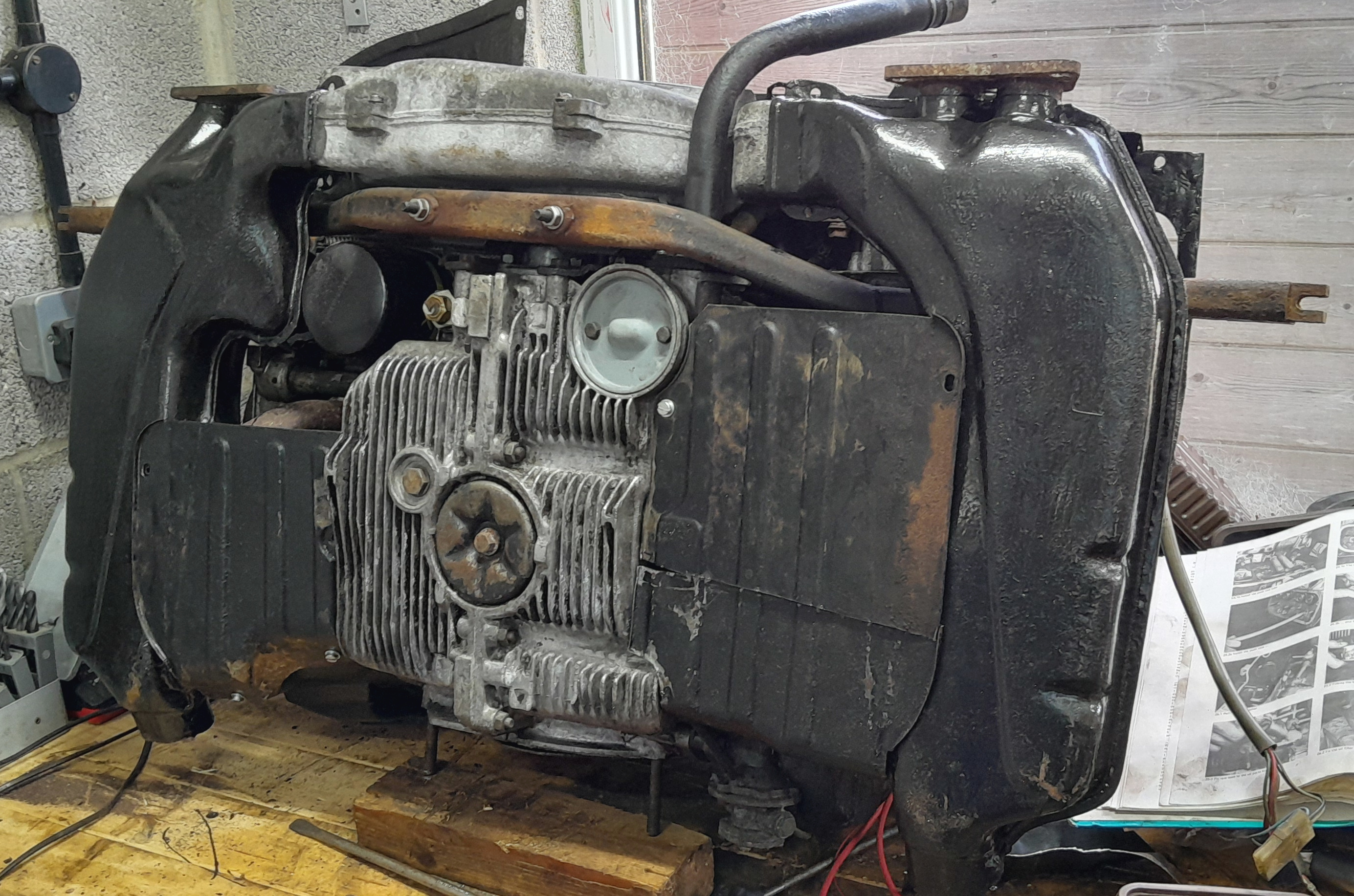 After several hours work, the picture on the left is where I got to. The left hand side cover is an inch or so shorter than it should be but I think I can live with it. The right hand side will need the joint welding after it’s tidied up a bit.
 To the right here, job done.
Whilst fitting these I discovered another wrinkle – the Manual said to fit the left hand heat exchanger then the engine support bar and then the right hand heat exchanger. Well it doesn’t work like that! The bar has to go on before both of the heat exchangers. It needs a lick of paint.
With all this extra stuff bolted onto the engine, it has now become very heavy. The heat exchangers in particular have added a lot!
To be continued . . .